Mico Lock Wiring Diagram
Home Service Documents Service Instructions Lever Lock Installation and Service Instructions. Push button release electric strike.
Multi Print 2 9 15 Flip Ebook Pages 1 12 Anyflip Anyflip

Coded wiring diagrams and a specific 691 ModelsReplacement Parts Table are also included.

Mico lock wiring diagram. These locks help a vehicles parking brake by using the dual or split hydraulic service brake system. The MICO 690 brake lock system is state of the art in supplemental brake holding. MICO Elite Range is the ideal choice where security is paramount.
AutoShift 18-Speed Wiring Diagram with Push Button Shifter. MICO 691 Lock System Manual Form Number 81-690-032 This 24-page service manual includes installation operating and trouble shooting information. If all is still clear slowly rotate the knob clockwise to.
These locks include adjustable sec relock time delay and a. MICO Inc1 Form No. Supplied as standard operation of Access Control in and out for full audit trail.
Tested and approved on selected single and double doorsets to LPCB SR 2345 6. Two single doors with panic bars. 81620016 Brake Lock Electric Activatedpdf.
This unit is handed as per diagram below add code when ordering. The MICO Abryll Range has established itself as the most approved Single Point Locking Range for high security applications. Ratings gained on selected locks on selected doorsets.
Using a flat-head screwdriver loosen the four captive screws that secure the display cover to the housing. The green light will illuminate. Press the green button to activatepower the panel.
MICO 691 Lock System Manual. Wiring 3 Wiring 31 Connect input and output wiring Figure 3-1 shows the location of the wiring terminals on the Model 3350 or Model 3700. Wiring diagram for QEL panics mag lock wiring diagrams.
You will find a green ON button and a red OFF button. Abryll EM 3Abryll EM 1 SATEAbryll EM 3 SATE The MICO Abryll Single Point Electro-Mechanical Range to be used with any 12v Access Control System. The internal Breakdome or external Key.
Electric Lock Installation and Service Instructions. The CHARGE is the most advanced power management available that does the work of three devices -- a traditional battery charger a charge-on-the-run an emergency start system--all in one compact unit. Button by pressing in the safety lock on the left side of the switch and then lifting up.
1 UltraShift DM3 6-Speed Wiring Diagram with Analog Shifter UltraShift DM3 6-Speed Wiring Diagram with Analog Shifter Gear select motor Rail select motor Electric shifter A B A B Rail select sensor Gea r10 select sensor Input shaft speed sensor Output shaft. Larger diagram In this example the manual labeled the blue wire leaving the 6-pin connector as the negative. The following common wiring diagrams are available.
Manufactured from Stainless Steel as standard the Abryll Range offers a robust high security solution for even the harshest environments. This 24-page service manual includes installation operating and trouble shooting information. Wiring diagram request form.
Lever Lock Installation and Service Instructions. It is a new brake lock concept that operates as a self contained electrohydraulic actuation system. Connect inputoutput wiring to the appropriate terminals on the gray terminal block.
Lever locks for fire doors. Complete Diagnosis Operation and Test Service Manual with Electrical Wiring Diagrams for John Deere 410G Backhoe with all the shop information to maintain test repair service like professional mechanics. Two single doors with panic bars.
Coded wiring diagrams and a specific 691 ModelsReplacement Parts Table are also included. POWER-POLE CHARGE MARINE POWER MANAGEMENT STATION THE ALL-IN-ONE CHARGE ON THE RUN SMART CHARGER. Shop our Mico Brake Locks for supplemental parking and to be used in conjunction with a vehicles mechanical parking brake.
It can be configured to offer full entry in and out or entry in with Emergency Escape out when fitted with our SATE option. NOTE All 691 models include the self adhesive labels shown below. 30mm bolt projection 25mm bolt throw.
81-690-032 Revised 2018-11-19 Use in all applications where the 691 System is remotely activated. Option 1 - Push Pad Option 2 - Full Width Push Plate. 1911 Lee Boulevard North Mankato MN USA 56003-2507.
Standalone with access control and Magnetic Lock Wireless Multi-Technology Reader - GCK Magnetic Lock Setup Guide Diagram from the manual that shows where to connect wires. The 690 supplements a vehicles mechanical parking brake by utilizing the service brake system. Choose from lever lock dual cable brake lock lock repair kit lock switch kit single brake lock and more made by Mico.

Honda Xl100 Motorcycle Complete Wiring Diagram All About Wiring Diagrams Electrical Wiring Diagram Motorcycle Paint Jobs Honda
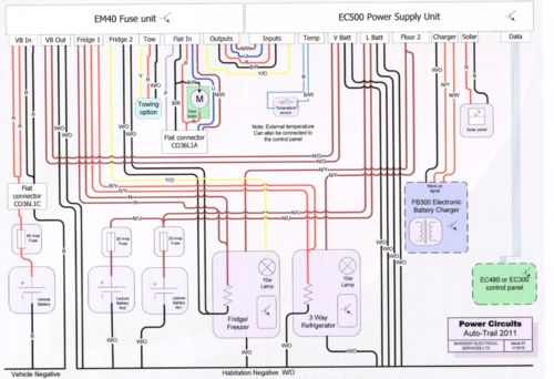
Autotrail Users

Pin On Electronics
Focus Wiring Vehicles Machines


15 Home Electric Fence Wiring Diagram Wiring Diagram Wiringg Net

Custom Cruiser Rahmen Tsp Wave Hc 130mm Limited Edition Demon Gabel Hc Classic Cycle En Bike Frame Lowrider Bike Custom Bicycle

Mico Product Training Session 9 Hydraulic Brake Locks Youtube
Focus Wiring Vehicles Machines

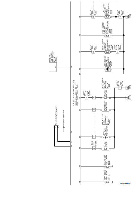
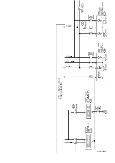
Wiring Diagram Door Lock Type 1 Nissan Juke Service And Repair Manual

18 Electrical Door Interlock Wiring Diagram Wiring Diagram Wiringg Net Door Locks Magnetic Door Lock Electrical Wiring Diagram

Remote Control Electrical Diagram

18 Car Central Lock Wiring Diagram Alarmas Para Autos Cosas De Coche Coches Personalizados
41 Pdf Vehicle Parts Wheeled Vehicles

Material Required For Portable Eeg System Development Circuit Diagram Brain Waves Circuit Design
Wiring Diagram Door Lock Type 1 Nissan Juke Service And Repair Manual
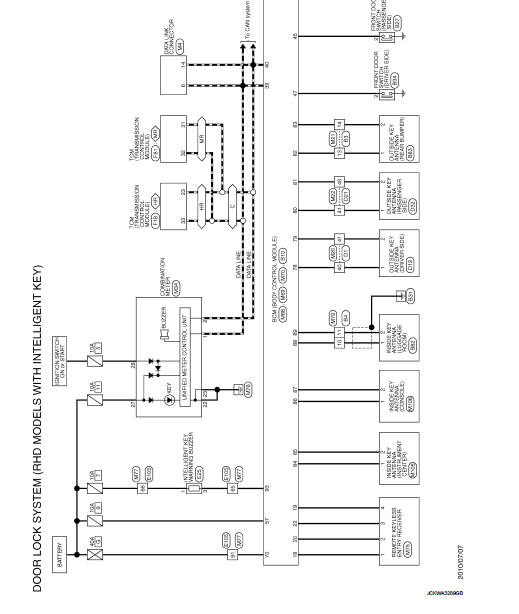
Wiring Diagram Door Lock Type 1 Nissan Juke Service And Repair Manual

Mini Chopper Plans Mini Motorcycle Plans Mini Bike Mini Chopper Motorcycle Mini Chopper Chopper Motorcycle

Pin On Car Ecu
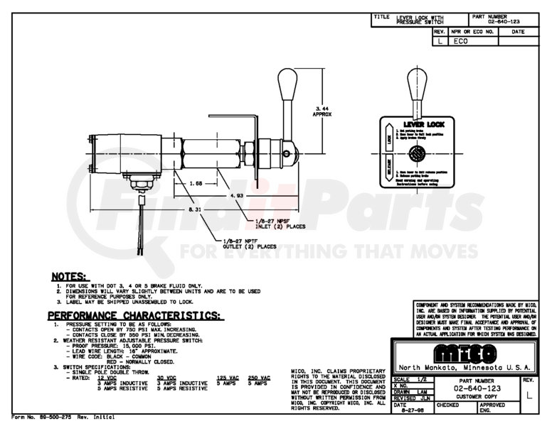
02 640 123 By Mico Lever Lock Please Allow 7 Days For Handling If You Wish To Expedite Please Call Us
Posting Komentar untuk "Mico Lock Wiring Diagram"